How to Manage Facade Thermal Bridging: The Definitive Engineeri
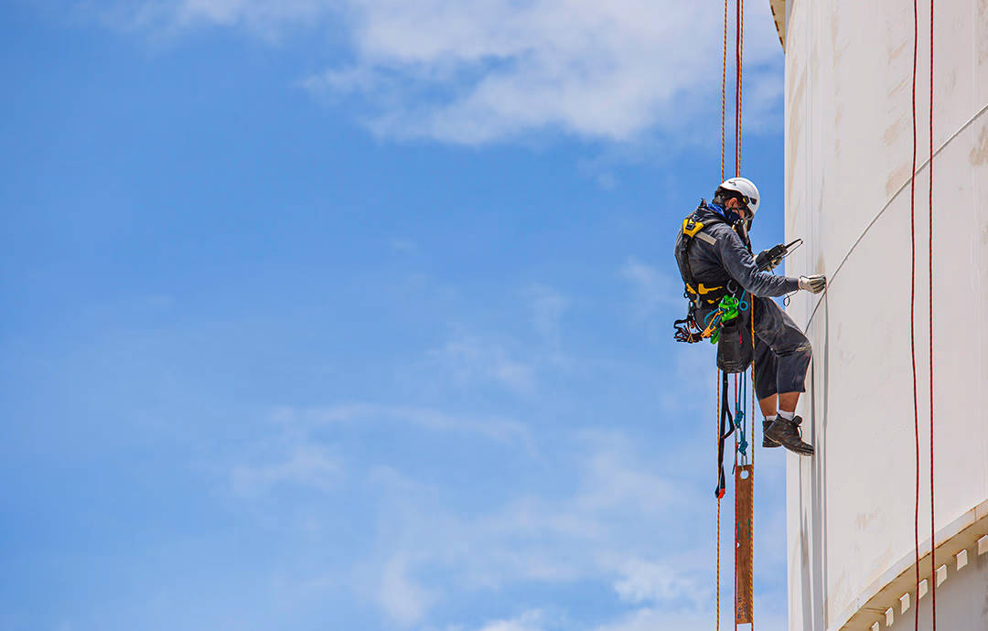
The architectural envelope is frequently compromised by an invisible efficiency killer: the thermal bridge. In the rigorous pursuit of high-performance building design, the facade is often conceptualized as a continuous shield, yet the reality of structural necessity introduces thousands of penetrations—anchors, brackets, slab edges, and fasteners—each acting as a thermal highway. How to Manage Facade Thermal Bridging. These pathways allow heat to bypass even the thickest layers of insulation, undermining energy models and creating localized zones of risk for condensation and structural degradation.
Managing these vulnerabilities requires moving beyond the basic calculation of R-values to a more granular understanding of heat flux. As building codes worldwide transition toward net-zero standards, the tolerance for “unaccounted-for” thermal losses is vanishing.
This exploration delves into the sophisticated engineering required to maintain thermal continuity in complex building skins. It is an investigation into the physics of heat transfer at the junctions where the building’s skeleton meets its skin. By examining the technical strategies used to decouple these systems, we can begin to understand the nuances of creating a truly high-performance envelope that survives the test of both climate and time.
Understanding “how to manage facade thermal bridging”
At its core, learning how to manage facade thermal bridging is an exercise in identifying and interrupting conductive paths. A common misunderstanding in the industry is that adding more insulation to a wall assembly will linearly increase its performance. However, if the insulation is interrupted by a series of metal “Z-girts” or cantilevered concrete balconies, the effective R-value of that wall can plummet by as much as $50\%$ to $70\%$. This is known as the “shunting” effect, where heat takes the path of least resistance through the conductive bridge.
The complexity of management is further compounded by the distinction between linear and point thermal bridges. Linear bridges occur at consistent junctions, such as the interface between a window frame and a rough opening, while point bridges are localized, such as the individual bolts securing a curtain wall to a floor slab. Oversimplification often leads designers to focus on the large, visible bridges while ignoring the cumulative impact of thousands of small fasteners. A truly definitive reference for this discipline must emphasize that thermal bridging is a three-dimensional problem; heat does not just move through a wall, it moves around corners and through structural connections in ways that two-dimensional drawings fail to capture.
Risks of mismanagement extend far beyond high utility bills. When a thermal bridge remains unaddressed, the interior surface temperature of the building skin can drop below the dew point of the indoor air. This leads to interstitial condensation—moisture that forms inside the wall assembly where it cannot be seen. Over time, this leads to mold growth, the rot of organic materials, and the corrosion of the very metal components that created the bridge in the first place. Therefore, thermal bridging management is as much about building longevity as it is about energy conservation.
Deep Contextual Background: The Rise of the Conductive Shell
In the era of traditional masonry construction, thermal bridging was largely mitigated by the sheer thickness of the walls. Stone and brick have lower thermal conductivity than modern steel, and their mass provided a buffer that smoothed out temperature fluctuations. As architecture evolved toward the “International Style” and the use of lightweight curtain walls, the building skin became a thin membrane of glass and aluminum. Aluminum, while lightweight and durable, is a phenomenal conductor of heat, possessing a thermal conductivity roughly 1,000 times higher than most insulation materials.
The 1970s energy crisis sparked the first serious attempts at “thermal breaks”—inserting a non-conductive material, like plastic or reinforced nylon, between the interior and exterior halves of a metal frame. However, these early attempts were often structurally weak or failed under UV exposure. Today, we are in the third generation of thermal management, where we utilize aerospace-grade composites and high-performance foams to create structural connections that are thermally “invisible.” The context has shifted from a luxury consideration to a regulatory mandate, as modern codes now require “effective R-value” reporting, forcing the industry to confront the reality of heat bypass.
Conceptual Frameworks and Mental Models
To master the management of heat transfer, engineers utilize specific mental models to categorize and solve bridging issues.
-
The Thermal Pen Rule: If you cannot trace a continuous line of insulation around a building section without lifting your pen, you have a thermal bridge. This model forces a focus on continuity rather than thickness.
-
The “Path of Least Resistance” Model: Heat behaves like water; it will find the smallest crack or the most conductive material to escape. This framework prioritizes the “weakest link” in the assembly over the average performance.
-
The Isothermal Mapping Framework: Visualizing the building skin as a topographic map of temperatures. Where the lines (isotherms) bunch together, the temperature gradient is steep, indicating a high-risk area for energy loss and condensation.
-
The Structural-Thermal Decoupling Model: This model assumes that the structural needs of the building and the thermal needs are in permanent opposition. The goal is to minimize the “touch points” between the two systems using high-strength, low-conductivity spacers.
Key Categories of Thermal Management Strategies
Interrupting the thermal bridge requires a diverse toolkit of materials and assemblies, each with specific trade-offs regarding cost, strength, and ease of installation.
| Strategy Type | Mechanism | Primary Advantage | Significant Trade-off |
| Structural Thermal Breaks (STB) | Insulated connectors for balconies/canopies | Eliminates major slab-edge bridges | High upfront hardware cost |
| Non-Conductive Z-Girts | Fiberglass or composite cladding supports | Improves wall R-value by 40%+ | Increased wall thickness |
| Aerogel Spacers | Ultra-thin, high-resistance strips | Fits in tight tolerances | Fragile; high cost per inch |
| Offset Brackets | Reducing the contact area of anchors | Minimizes point bridging | Requires complex structural calc |
| Polyamide Strips | Mechanical separation in extrusions | Industry standard for windows | Limited to specific widths |
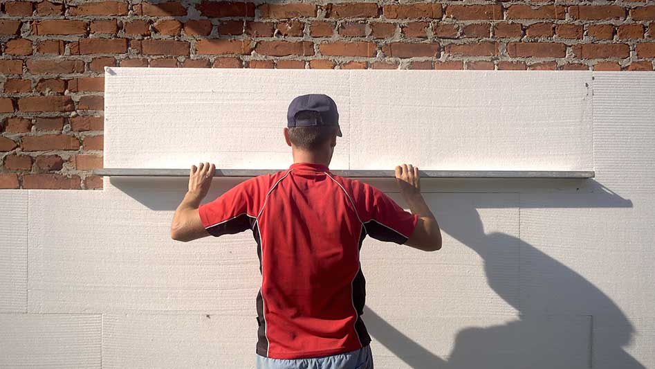
| Continuous Exterior Insulation | Placing all insulation outside the studs | Simplest “blanket” approach | Challenges with cladding attachment |
Decision Logic: Balcony and Slab Edge Transitions
The most aggressive thermal bridges are often found at cantilevered balconies. A concrete slab that runs from the warm interior to the cold exterior acts like a giant radiator fin. For high-rise residential projects, the latter is increasingly becoming the only viable way to meet strict energy performance targets.
Detailed Real-World Scenarios How to Manage Facade Thermal Bridging
Scenario 1: The High-Rise Window-to-Wall Interface
A luxury residential tower in a cold climate features floor-to-ceiling glass. The gap between the window frame and the floor slab is a primary thermal leak.
-
Failure Mode: Using standard spray foam without a structural thermal spacer.
-
Decision Point: Implementing a reinforced polyamide “panning” system that bridges the gap between the curtain wall and the interior floor finish.
-
Second-Order Effect: Improved acoustic performance, as the thermal break also acts as a vibration isolator between the facade and the structure.
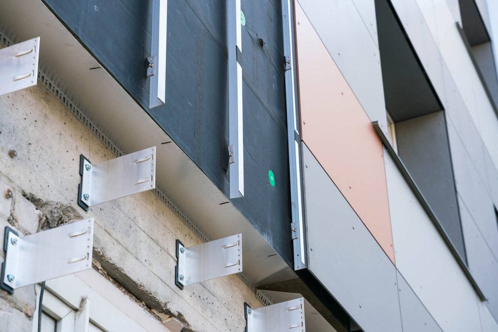
Scenario 2: The Perforated Metal Cladding System
An institutional building uses a custom perforated metal skin held away from the wall by hundreds of steel brackets.
-
Constraint: Each bracket creates a point thermal bridge that causes “shadowing” or dark spots on the interior drywall due to localized condensation.
-
Solution: Inserting a thermal shim (typically high-density polyethylene) between each bracket and the building’s weather barrier.
-
Risk: Ensuring the shims do not compress over time, which would cause the cladding to sag.
Planning, Cost, and Resource Dynamics
The economics of thermal management are often obscured by a focus on material costs rather than operational savings. While a non-conductive girt system may cost $30\%$ more than a galvanized steel version, the reduction in required HVAC capacity can often offset this capital expense during the construction phase.
Cost and Performance Variability Table
| Mitigation Level | Cost Impact (on facade) | R-Value Improvement | Ideal Application |
| Basic (Thermal Washers) | $+1\% \text{ to } +3\%$ | $5\% \text{ to } 10\%$ | Standard commercial |
| Intermediate (Composite Girts) | $+5\% \text{ to } +12\%$ | $25\% \text{ to } 40\%$ | Schools, Healthcare |
| Advanced (Structural Breaks) | $+15\% \text{ to } +25\%$ | $50\% \text{ to } 80\%$ | Passive House, High-End Res |
| Extreme (Aerogel/Vacuum) | $+40\%+$ | $90\%+$ | Art Galleries, Labs |
Tools, Strategies, and Support Systems
The modern engineer relies on computational tools to predict and prevent thermal bridging before a single bolt is turned on site.
-
2D Heat Transfer Modeling (THERM): A foundational tool for analyzing the cross-sections of window frames and wall junctions to calculate U-factors.
-
3D Finite Element Analysis (FEA): Essential for point bridges, such as complex corners or custom anchor assemblies where 2D models fail to account for lateral heat flow.
-
Infrared Thermography: Used during the commissioning phase to “see” heat leaks in the finished building.
-
Hygrothermal Analysis (WUFI): Simulates the movement of moisture alongside heat, predicting if a thermal bridge will cause rot over a 10-year period.
-
Thermal Shim Kits: Pre-sized pads made of materials like PTFE or reinforced fiberglass, designed to be inserted behind facade anchors.
-
Low-Conductivity Fasteners: Stainless steel or coated fasteners that reduce heat transfer compared to standard carbon steel.
Risk Landscape and Failure Modes
The taxonomy of risks in thermal bridging management is not merely about temperature, but about the compounding effects of moisture and structural fatigue.
-
Ghosting and Soiling: Localized cold spots on interior walls attract dust and particulates via “thermophoresis,” creating dark patterns that look like mold but are actually accumulated dirt.
-
Differential Thermal Expansion: If the exterior cladding is thermally decoupled from the structure, it will reach much higher temperatures in summer and lower in winter than the building frame. The anchors must be engineered to allow for this increased movement without snapping.
-
Hidden Mold Growth: When the dew point occurs inside a stud cavity due to a thermal bridge, mold can grow for years behind the drywall, only becoming apparent when occupants report respiratory issues.
Governance, Maintenance, and Long-Term Adaptation
The thermal integrity of a facade must be managed as a long-term asset. Governance involves regular “health checks” of the thermal envelope to ensure that settling or maintenance work hasn’t compromised the original design.
Layered Maintenance Checklist
-
Post-Installation Audit: Use a thermal camera during the first winter to verify that all structural thermal breaks were installed correctly and not “shorted” by accidental metal-on-metal contact.
-
Sealant Integrity Review: Inspect the joints around thermal breaks every 5 years. If the weather seal fails, water can saturate the thermal break, potentially reducing its effectiveness.
-
Retrofit Triggers: If a building undergoes a window replacement, it should trigger a mandatory review of the perimeter thermal bridging, as this is the only time these junctions are exposed.
Measurement, Tracking, and Evaluation
Quantifying the success of thermal management requires a mix of simulation and empirical data.
-
Leading Indicator: The “Psi-Value” ($\psi$) of junctions. This is a measure of linear thermal transmittance. A successful project will have specific Psi-value targets for every major junction (e.g., roof-to-wall, window-to-wall).
-
Qualitative Signal: Interior surface temperature consistency. If the temperature of the wall varies by more than $3^\circ\text{C}$ near a junction, the thermal bridge is insufficiently managed.
-
Quantitative Documentation: Comparison of predicted energy use versus actual sub-metered heating data over a two-year cycle.
Common Misconceptions and Oversimplifications
-
“Spray foam solves everything”: While foam is a great insulator, it does not stop heat from moving through the metal studs or anchors that penetrate it.
-
“Thermal bridges are only a cold-climate problem”: In hot climates, thermal bridges work in reverse, “importing” heat into a cooled building and causing condensation on the outside of the vapor barrier.
-
“The air gap is an insulator”: In a rainscreen system, the air gap is ventilated. This means the air is the same temperature as the outside, and it provides zero thermal resistance.
-
“Standard stainless steel is a thermal break”: While stainless steel is less conductive than carbon steel, it is still a conductor. True management requires a non-metallic break.
-
“The R-value on the box is what I get”: The value on the insulation packaging is the “nominal” value. The “effective” value is almost always lower once bridging is factored in.
Ethical and Practical Considerations
There is an ethical dimension to thermal bridging. Occupants of buildings with severe thermal bridges often suffer from “thermal discomfort”—feeling a cold draft even when the thermostat says $21^\circ\text{C}$. This is because our bodies radiate heat toward cold surfaces. By failing to manage thermal bridging, designers effectively pass on a “comfort tax” to the tenants, who must over-heat their spaces to compensate for cold walls.
Conclusion
Mastering how to manage facade thermal bridging is one of the most technical and rewarding aspects of modern architectural engineering. It requires a shift in perspective, viewing the building not as a collection of materials, but as a dynamic energy system. The invisible work of thermal decoupling is, in many ways, the most important work a facade engineer can perform.