How to Avoid Facade Structural Risks: The Definitive Engineering
The structural integrity of a building’s facade is often a matter of silent performance. While the primary skeleton of a tower—the columns, slabs, and cores—receives the bulk of engineering scrutiny during the conceptual phase, the exterior envelope is frequently treated as a secondary architectural skin. This perspective is fundamentally flawed. How to Avoid Facade Structural Risks. In the modern high-rise context, the facade is a massive, complex structural assembly subjected to relentless environmental forces, ranging from extreme wind pressures to seismic accelerations and significant thermal expansion.
When we consider the transition from traditional masonry to lightweight, high-performance curtain walls, the nature of structural risk shifts. We are no longer dealing with a “thick” wall that fails through gradual cracking, but with a series of interconnected, highly stressed components where a single failed bracket or a brittle sealant can lead to a catastrophic detachment. As buildings push higher into the troposphere, these risks escalate. The wind doesn’t just push against a building; it creates complex vortices and suctions that can literally pull panels away from their anchors if the physics of the assembly is misunderstood.
Achieving a resilient envelope requires a move toward forensic-level engineering during the design phase. It involves a deep investigation into the “load path”—tracing exactly how the weight of the glass and the pressure of the wind travel through the aluminum extrusions, into the steel brackets, and finally into the concrete slab. To succeed, designers and developers must navigate a landscape of conflicting priorities: the desire for maximum transparency versus the need for structural stiffness, and the push for rapid installation versus the necessity of millimetric precision.
How to Avoid Facade Structural Risks
To define the methodology of how to avoid facade structural risks, one must first discard the notion that the facade is a non-structural element. In engineering terms, the envelope is a “secondary structure,” yet its failure is often more public and dangerous than failures in the primary frame. A common misunderstanding in the industry is that code compliance equals safety. In reality, building codes provide a minimum baseline; they often fail to account for the specific micro-climatic turbulence of a unique urban site or the long-term chemical degradation of structural adhesives.
Oversimplification in this field often centers on “dead loads”—the weight of the materials. While gravity is a constant, the dynamic loads (wind, seismic, and thermal) are where the true risks reside. For instance, thermal expansion can generate thousands of pounds of force within a restrained aluminum frame. If the drafting does not include “expansion joints,” the frame will eventually buckle or shear its own bolts. Professional risk mitigation focuses on these “invisible forces,” ensuring that the system has enough “play” to move without losing its structural grip.
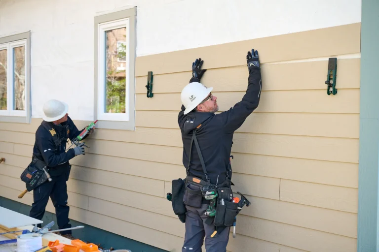
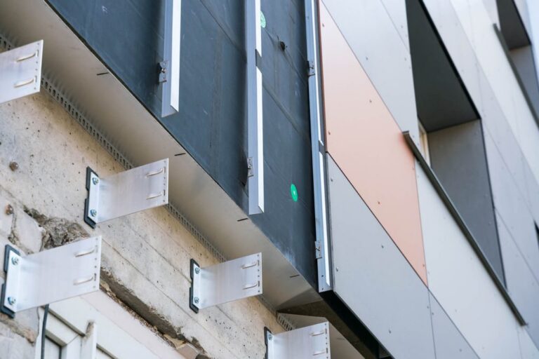
The risk of ignoring the nuance of load paths is particularly acute in “unitized” systems. Because these panels are pre-fabricated and simply hung on the building, the connection point—the “stack joint”—becomes the most critical structural node. If the anchor is misaligned by even half an inch, the load is transferred unevenly, creating a twisting force (torsion) that the bracket was never designed to handle. True mastery in risk avoidance lies in managing these tolerances through rigorous site observation and digital coordination.
The Systemic Evolution of Envelope Load Management
The history of the facade is a story of the separation of functions. In the nineteenth century, the wall was the structure. Gravity was the primary enemy, and thickness was the primary defense. The advent of the steel frame “liberated” the wall, allowing it to become a thin, lightweight curtain. However, this liberation introduced a new set of structural vulnerabilities: the system became highly susceptible to wind-induced vibrations and the “pumping” action of air pressure.
In the mid-twentieth century, the industry moved toward standardized aluminum curtain walls. These early systems often failed because they didn’t account for the “differential movement” between the facade and the building’s primary frame. As concrete slabs “creep” and shorten over time, they can crush the facade panels sitting between them. The evolution of the “split-mullion” unitized system was the technical answer to this problem, allowing panels to slide past each other while maintaining a structural and weather-tight seal.
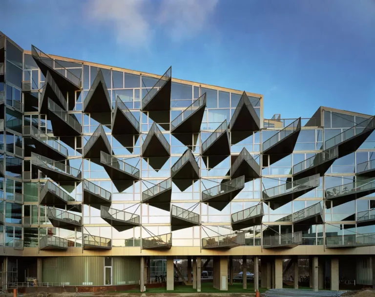
Today, we are in the era of “supertall” re-engineering. We are seeing facades that incorporate structural glass fins, cable-net systems, and complex parametric geometries. These designs require a move away from “rule-of-thumb” engineering and toward Computational Fluid Dynamics (CFD) and wind-tunnel testing. The evolution highlights a shift from material strength to “systemic resilience”—the ability of a facade to absorb energy and movement without a brittle failure.
Conceptual Frameworks and Structural Mental Models
Specialists utilize specific frameworks to ensure that no force is left unaccounted for in the envelope assembly.
1. The Redundant Load Path Framework
This model assumes that any single connection can fail. The goal is to design a “fail-safe” system where, if one anchor fails, the surrounding anchors can temporarily redistribute the load. This is particularly critical for overhead glazing or high-rise glass where the “brittle” nature of the material offers no warning before failure.
2. The Thermal Expansion Loop
Metal and glass expand at different rates. This framework treats the facade as a “living” machine that grows and shrinks every day. A successful design ensures that no two dissimilar materials are “locked” together in a way that prevents this movement. When materials are locked, the internal stress (hoop stress) can lead to spontaneous glass breakage or metal fatigue.
3. The Pumping and Fatigue Model
Wind doesn’t just push; it oscillates. This model evaluates the “cyclic loading” on the facade. Just as a paperclip breaks after being bent back and forth, the aluminum brackets and sealant beads can fail through fatigue if they are subjected to constant vibration. Risk mitigation involves dampening these vibrations and selecting materials with high fatigue resistance.
Key Categories of Facade Systems and Structural Trade-offs
The choice of system dictates the structural “DNA” of the project and determines where the risks are concentrated.
| System Type | Structural Logic | Primary Risk | Trade-off |
| Unitized Curtain Wall | Panels hung from slabs; interlocking joints. | Anchor alignment; stack joint movement. | High speed; requires extreme precision. |
| Stick System | Assembled on-site piece by piece. | Labor quality; weather-exposed seals. | Flexible for geometry; slow installation. |
| Structural Glass Fins | Glass acts as the support beam. | Brittle failure; “Nickel-Sulfide” inclusions. | Maximum transparency; very high cost. |
| Point-Supported (Spider) | Glass held by mechanical bolts. | Stress concentration at holes. | Sleek aesthetic; complex engineering. |
| Window Wall | Sits between slabs (not bypassed). | Slab-edge deflection; air leakage. | Lower cost; higher movement risk. |
Decision Logic: The Stiffness-to-Weight Ratio
In high-rise engineering, “stiff” is not always better. A facade that is too stiff will attract more force and is more likely to crack or shear under seismic or wind loads. The ideal structural logic is “controlled flexibility”—a system that is stiff enough to prevent glass from breaking but flexible enough to move with the building’s primary frame.
Detailed Real-World Scenarios How to Avoid Facade Structural Risks
Scenario 1: The “Creeping” Concrete Slab
In a 50-story concrete tower, the concrete slabs naturally “shrink” over the first five years of the building’s life.
-
The Risk: If the unitized facade panels do not have enough vertical “expansion gap” at the stack joint, the shrinking building will eventually put the facade in “compression,” causing the glass to explode.
-
The Decision Point: Specifying a 20mm gap instead of a 10mm gap, even if it complicates the aesthetic of the horizontal line.
-
Failure Mode: Buckling of the vertical mullions.
Scenario 2: The “Negative Pressure” Suction
On the corners of a rectangular high-rise, wind creates a “vortex” that pulls outward on the panels with more force than it pushes inward.
-
The Risk: Standard anchors are often stronger in “push” than in “pull.”
-
The Analysis: Wind tunnel testing reveals that corner panels require twice as many anchors as center panels.
-
Failure Mode: Panels detaching and falling to the street below during a storm.
Planning, Cost, and Resource Dynamics
The economics of facade structural safety are governed by the cost of “remediation.” Replacing a failed anchor during construction costs a few hundred dollars; replacing it on a finished, occupied 40th floor requires custom swing-stages and costs tens of thousands.
Investment Range for Structural Mitigation
| Component | Cost Impact | Variable Factors |
| Wind Tunnel Testing | $30k – $100k | Building height; surrounding terrain. |
| Structural Silicone Testing | $10k – $25k | Adhesive brand; material compatibility. |
| Third-Party Peer Review | 1% of facade cost | Complexity of the geometry. |
| On-site “Pull Tests” | $5k – $15k | Number of anchor types. |
Technical Support Systems and Diagnostic Tools
Modern engineering utilizes a suite of tools to move from “calculated” safety to “verified” safety.
-
Finite Element Analysis (FEA): Modeling the exact stress points in a custom aluminum extrusion or a glass fin to see where it will break first.
-
Structural Silicone Adhesion Testing: Ensuring that the “glue” holding the glass to the frame actually bonds to the specific coating of that glass.
-
Total Station Surveying: Using laser coordinates to ensure the concrete slab edge is exactly where the drawings say it is before the facade is hung.
-
Borescope Inspection: Looking inside “closed” systems to verify that the internal bolts were actually installed and tightened.
-
Dynamic Shaker Testing: Vibrating a mock-up of the facade to see if any screws shake loose under seismic or wind conditions.
-
Ultrasonic Testing: Checking the thickness of metal components and the integrity of welds without cutting into them.
The Risk Landscape: A Taxonomy of Failure
Facade structural risks are rarely isolated; they are “compounding.” A failure typically follows a specific taxonomy:
-
Design-Level Risks: Incorrect wind-load assumptions; failing to account for “eccentric loading” (when the weight is not centered on the bracket).
-
Material-Level Risks: Galvanic corrosion (when aluminum and steel touch and rot each other); “Nickel-Sulfide” inclusions causing spontaneous glass breakage.
-
Execution-Level Risks: “Overtorquing” bolts (weakening them); missing gaskets; misaligned anchors.
-
Environmental Risks: Excessive UV degradation of structural sealants; salt-air corrosion in coastal environments.
Governance, Maintenance, and Long-Term Adaptation
A facade is a “depreciating structural asset.” It requires a governance plan to ensure it remains safe over its 50-year lifespan.
-
The 5-Year Structural Audit: In many cities (like New York or Chicago), a “FACERS” or “FISP” inspection is legally required. This involves a “hands-on” inspection of the facade from a scaffold.
-
The Gasket/Sealant Lifecycle: Structural silicone typically has a 20-year warranty. A building governance plan must include a strategy for “re-sealing” or “re-clamping” the facade before the adhesive fails.
-
Monitoring Triggers: If residents report “whistling” or “rattling” during a storm, these are not just acoustic nuisances; they are leading indicators of structural movement or loose components.
Measurement, Tracking, and Evaluation Metrics
How do we quantify that we have avoided structural risk?
-
Leading Indicators: Percentage of anchors that pass “on-site pull tests”; number of “clashes” resolved in the BIM model before fabrication.
-
Lagging Indicators: Number of glass breakages per year; evidence of “sealant tear” during annual inspections.
-
Documentation: A “Structural Record of the Envelope”—a document that tracks every anchor’s location, the torque applied to its bolts, and the batch number of the sealant used.
Common Misconceptions and Oversimplifications
-
“Tempered glass is ‘unbreakable’.” It is stronger, but it is also more prone to spontaneous failure from internal impurities.
-
“The facade is held up by the windows.” No, the windows are “infill”; the load is carried by the “mullions” (the aluminum frame).
-
“Aluminum doesn’t rust.” It doesn’t rust like steel, but it “corrodes” and pits, especially when in contact with other metals or certain cleaning chemicals.
-
“Once it’s built, it’s safe.” Facades are dynamic. A building that was safe ten years ago can become dangerous if a new building is built nearby, changing the wind turbulence patterns.
Conclusion
The pursuit of how to avoid facade structural risks is an exercise in engineering humility. It requires an acknowledgment that the environment is more powerful than our materials and that the precision of our drawings is rarely matched by the reality of the construction site. A resilient facade is not one that is “indestructible,” but one that is designed with redundancy, flexibility, and a deep understanding of the invisible loads it must carry. By moving beyond the aesthetic surface and focusing on the rigorous physics of the load path, we ensure that our vertical landscapes remain as safe as they are spectacular. The integrity of the envelope is the final line of defense for the occupants within and the public below.