Facade Drafting and 3D Modeling Services: The Ultimate Pillar Guide
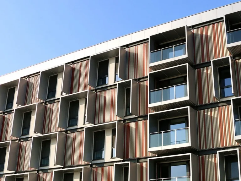
The architectural facade has evolved from a static exterior wall into a high-performance, multi-layered machine. In the contemporary construction landscape, the distance between an architect’s conceptual sketch and a structurally sound, weather-tight reality is spanned by the technical rigor of digital representation. Facade Drafting and 3D Modeling Services. As building geometries become more adventurous and environmental regulations more stringent, the traditional methods of hand-drafting and simple two-dimensional CAD have been rendered obsolete. We have entered an era where the virtual model is not just a picture of the building, but a data-rich simulation of its physical and mechanical existence.
The transition toward integrated digital workflows represents a fundamental shift in how we conceive of building boundaries. A facade is no longer treated as a singular surface; it is an assembly of thousands of unique components, each with its own thermal, structural, and acoustic properties. Managing this complexity requires a level of geometric precision that can only be achieved through advanced computational drafting. This process ensures that every bracket, gasket, and glass lite is accounted for before a single piece of material is fabricated in a shop or installed on a site.
Furthermore, the rise of the “digital twin” concept has extended the utility of facade modeling far beyond the construction phase. A well-constructed digital envelope serves as a long-term asset for building owners, facilitating predictive maintenance and energy performance tracking. This lifecycle-oriented approach to drafting ensures that the technical intelligence invested during the design phase continues to provide value for decades. Understanding the depth of this discipline is essential for anyone aiming to navigate the complexities of modern, large-scale high-rise or commercial developments.
Facade drafting and 3D modeling services
To accurately define Facade drafting and 3D modeling services, one must move past the idea that this is merely “drawing.” It is, in fact, the engineering of information. A common misunderstanding among developers is that drafting is a clerical task—a way to document what has already been decided. In reality, the modeling process is where the most critical design decisions are made. It is the stage where the theoretical “clashes” between the structural steel and the facade’s internal drainage system are identified and resolved.
Oversimplification in this field often leads to the “BIM-washing” trap, where a project is claimed to be fully modeled in 3D, but the model lacks the “Level of Detail” (LOD) necessary for fabrication. A superficial 3D model may look impressive in a presentation, but if it does not include the millimetric tolerances required for aluminum extrusions or the specific sealant depths for structural glazing, it is practically useless for construction. True technical services provide a “Level of Development” that bridges the gap between architectural intent and shop-floor manufacturing.
The risk of ignoring the nuance in these services is primarily financial. When the drafting is incomplete or inaccurate, the “resolution” of the design happens in the field—at the highest possible labor cost and with the lowest level of quality control. Professional modeling services prioritize the “front-loading” of effort. By investing in a high-fidelity 3D assembly during the pre-construction phase, stakeholders can virtually “build” the facade, identifying failure modes and logistical bottlenecks long before they become expensive site delays.
Historical Context: From Ink to Parametric Nodes
The history of facade documentation is a trajectory from the “static” to the “dynamic.” For centuries, facades were documented through stone-cutting patterns and hand-drawn sections. These drawings were artistic, but they were often interpretive; the master mason on-site held the ultimate technical authority. The industrial revolution brought standardized drafting, but the “information” remained trapped on two-dimensional paper, leading to significant coordination errors between different trades.
The introduction of Computer-Aided Design (CAD) in the 1980s digitized the lines but didn’t change the logic. It was still a flat representation. The real systemic shift occurred with the advent of Building Information Modeling (BIM) and Parametric Design. Instead of drawing a window, drafters now define a “family” of windows with specific data parameters—thermal U-values, glass thickness, and acoustic ratings.
Today, we are in the era of Generative Design. Designers use algorithms to “solve” for facade geometry based on environmental constraints like solar heat gain or wind pressure. This evolution reflects a broader cultural shift: we no longer just draw the facade; we program its behavior. The modern drafter is as much a data manager as they are a geometrician.
Conceptual Frameworks and Computational Mental Models
Technical experts in the field of envelope modeling utilize specific frameworks to ensure the integrity of the digital data.
1. The LOD (Level of Development) Hierarchy
This framework evaluates the “maturity” of a 3D model. LOD 100 might be a simple conceptual box, whereas LOD 400 includes every screw and gasket necessary for fabrication. A consultant must manage expectations by defining which LOD is required for each phase of the project to avoid “over-modeling” early on or “under-modeling” at the finish line.
2. The Clash-Detection Matrix
This mental model treats the building as a series of overlapping systems. The drafter isn’t just looking at the facade; they are looking at how the facade interacts with the HVAC ducts, the fire suppression system, and the structural slab. The goal is to ensure that no two physical objects occupy the same coordinate in digital space.
3. Parametric Associativity
This framework involves creating “links” between different parts of the model. If the floor height of the building changes in the master structural model, a parametrically associated facade model will automatically update all 5,000 panels to the new height. This reduces the risk of human error during the inevitable design revisions of a large project.
Key Categories of Modeling and Drafting Workflows
Modern workflows are categorized by the final “output” required by the client.
| Category | Primary Output | Best For | Trade-off |
| BIM/Revit Modeling | Data-rich 3D environment. | Coordination with other trades. | High file sizes; limited for complex curves. |
| Shop Drawing Drafting | Detailed 2D/3D fabrication instructions. | Manufacturing and site installation. | High labor intensity; site-specific. |
| Parametric Modeling (Rhino/Grasshopper) | Algorithmically driven geometry. | Complex, curved, or non-repeating facades. | Requires specialized coding skills. |
| Scan-to-BIM | 3D model generated from LiDAR laser scans. | Renovation and adaptive reuse. | Initial survey cost is high. |
| Digital Twin Simulation | Real-time operational model. | Long-term facility management. | Requires ongoing data input. |
Detailed Real-World Scenarios Facade Drafting and 3D Modeling Services

Scenario 1: The Non-Repeating Geometric Tower
A skyscraper features a “twisted” geometry where no two glass panels are the same size.
-
The Workflow: Drafters use parametric modeling to generate the dimensions for 4,000 unique panels automatically.
-
Failure Mode: If the drafting lacks “tolerance logic,” the panels may be theoretically correct but physically impossible to install due to on-site concrete variances.
-
The Solution: Integrating “site-survey” data directly into the 3D model before fabrication.
Scenario 2: The High-Performance Retrofit
An existing 1970s office building needs a new, energy-efficient skin.
-
The Workflow: Use Facade drafting and 3D modeling services combined with a LiDAR laser scan of the existing structure.
-
Constraint: The new facade must attach to an old, uneven concrete frame.
-
Second-Order Effect: By modeling the new facade against the “as-built” scan, the team can pre-engineer custom brackets that compensate for the old building’s sags and leans.
Planning, Cost, and Resource Dynamics
The financial planning for digital services is often misunderstood. While it represents a small percentage of the total construction budget, it has a massive impact on the “efficiency” of that budget.
Investment Variance Table
| Phase | Resource Required | Cost Impact | Potential Saving |
| Schematic Design | 3D Geometry Specialist | Low | Prevents unbuildable shapes. |
| Detailed Design | BIM Coordinator | Moderate | Reduces coordination errors by 30%. |
| Construction Docs | Technical Drafter | High | Prevents field-work delays. |
| Fabrication Modeling | LOD 400 Modeler | Very High | Minimizes shop-floor waste. |
Opportunity costs are critical here: every week a drafting team spends correcting “clashes” in the office saves a month of specialized labor fixing those same clashes on a crane 50 stories in the air.
Technical Tools, Strategies, and Support Systems
The “tech stack” for modern facade services is diverse and requires high-performance hardware and software integration.
-
Revit/BIM: The industry standard for multidisciplinary coordination and data management.
-
Rhino & Grasshopper: Used for generative geometry and managing complex surfaces that standard BIM software cannot handle.
-
SolidWorks/Inventor: Often used at the LOD 400 stage for the mechanical design of custom extrusions and metal parts.
-
Navisworks: A specialized tool for “Clash Detection” that merges models from architects, structural engineers, and MEP (mechanical, electrical, plumbing) teams.
-
Cloud-Based CDE (Common Data Environment): Systems like BIM 360 that allow drafters in different time zones to work on the same model simultaneously.
-
LiDAR Point Clouds: Using laser-scanned data to “ground” the 3D model in physical reality.
Risk Landscape and Taxonomy of Modeling Failures
Digital models can provide a false sense of security if the underlying logic is flawed.
-
The “Zero-Tolerance” Trap: Modeling components as “perfect” objects. In reality, steel moves, concrete shrinks, and wind pushes. A model that doesn’t include “installation tolerances” will fail in the field.
-
Coordinate Mismatch: When the architect’s model uses a different “origin point” than the structural engineer’s model. This can lead to the facade being modeled 2 feet away from where the building actually is.
-
Data Bloat: Including too much unnecessary detail (like modeled threads on every screw) can make the model files so heavy they become impossible to open, crashing the project’s digital infrastructure.
-
Version Control Failure: Using an outdated structural model to design the facade, leading to thousands of fabricated parts that no longer fit the revised building shape.
Governance and Long-Term Adaptation
A facade model should be treated as a “living document.” Governance involves strict protocols for who can change the model and how those changes are verified.
-
Audit Cycles: Every two weeks, the model should undergo a “Health Check” to ensure it adheres to the project’s BIM standards.
-
Change Triggers: Any change in the structural slab must trigger an automatic review of the facade anchors.
-
Layered Documentation: The model should be organized so that maintenance teams 20 years from now can “hide” the glass and “see” the internal anchors to check for corrosion.
Measurement and Evaluation Metrics
How do you measure the “quality” of Facade drafting and 3D modeling services?
-
Leading Indicators: The number of RFI (Requests for Information) during the drafting phase (more is better here, as it means questions are being answered early).
-
Lagging Indicators: The “Field Error Rate”—the percentage of panels that arrive on-site and cannot be installed because they don’t fit.
-
Clash Resolution Rate: Tracking how many digital conflicts were resolved before the fabrication drawings were signed off.
Common Misconceptions and Oversimplifications
-
“3D modeling is just for looking at.” In truth, it is for extracting data—quantities of materials, thermal values, and manufacturing instructions.
-
“Software does the work.” Software is just a tool. The quality of a model depends entirely on the technical building-science knowledge of the person driving the software.
-
“2D is dead.” While we model in 3D, the site workers still need clear, high-quality 2D “Shop Drawings” extracted from that model to do their jobs.
-
“BIM is too expensive for small projects.” The cost of BIM is always lower than the cost of one major field error.
Conclusion
The evolution of Facade drafting and 3D modeling services marks the end of the “guesswork” era in construction. As our buildings grow more complex and our environmental responsibilities more heavy, the digital blueprint has become the primary site of engineering judgment. By virtualizing the building envelope with high-fidelity data, we reduce waste, ensure safety, and create a permanent technical record of the structure. The integrity of a modern building is no longer just in its materials, but in the precision of the data that defines how those materials come together. In the vertical frontier, the model is the foundation.